") Our HotMicroCoil heating elements can be used in a wide variety of applications. Their high level of plasticity ideally suits them to the heating of
hot runner nozzles and for accurately heating the contours of three-dimensional surfaces. Many of our customers order HotMicroCoil elements in their unformed state and
perform the subsequent shaping work themselves, while others commission us to shape and fit the elements. A large number of ready-to-fit system solutions are available
for plastic injection nozzles with clamping mechanisms, housing bezel, reflection tube or heat conduction sleeve.
Our HotMicroCoil heating elements can be used in a wide variety of applications. Their high level of plasticity ideally suits them to the heating of
hot runner nozzles and for accurately heating the contours of three-dimensional surfaces. Many of our customers order HotMicroCoil elements in their unformed state and
perform the subsequent shaping work themselves, while others commission us to shape and fit the elements. A large number of ready-to-fit system solutions are available
for plastic injection nozzles with clamping mechanisms, housing bezel, reflection tube or heat conduction sleeve.
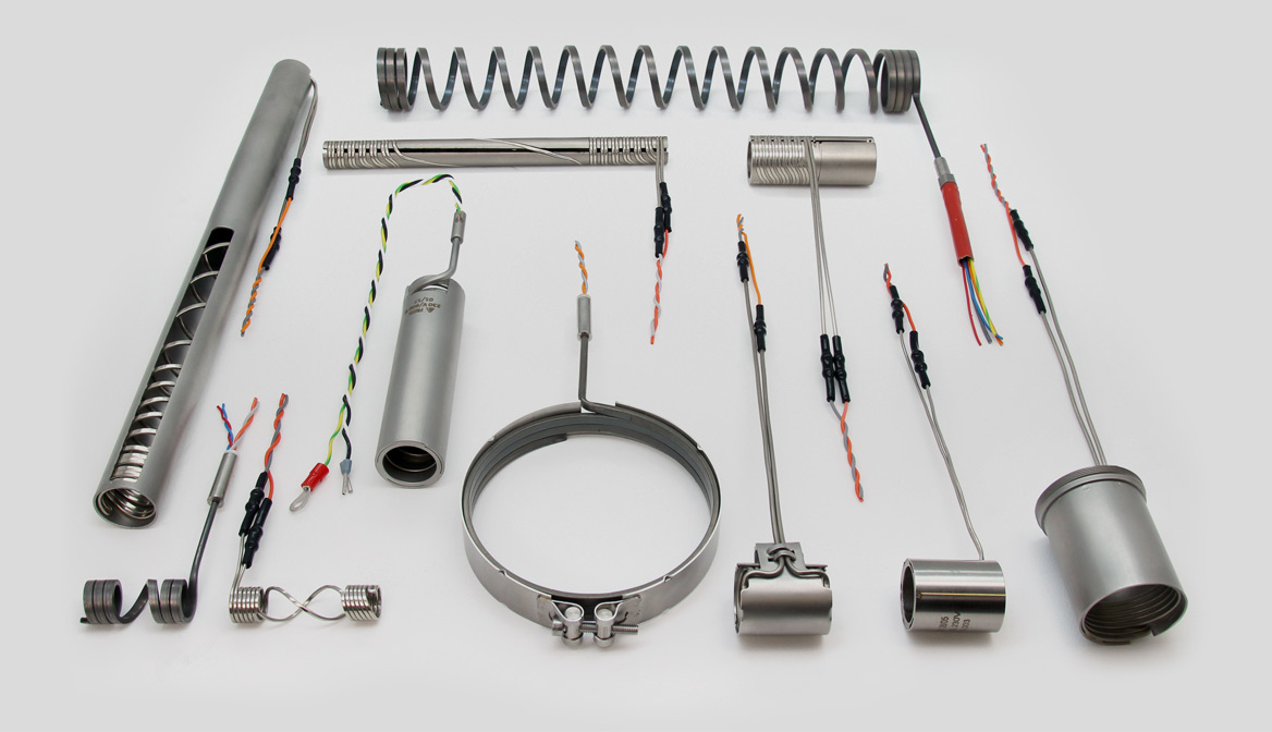
In micro-injection moulding systems and high-performance tools with small cavity spacings, the preferred elements are MicroCoils, which are as thin as 1 mm, while where there is more space in the hot runner or the heat demand is higher, the more powerful HotCoils are used. With its larger cross-section, the latter type has its connection point at one end as standard, and a Type J or K thermocouple can also be integrated on request.
HotMicroCoils bearing the 'freek' brand use exclusively the highest-quality raw materials and high-precision components. Motivated and qualified employees process these parts within a refined production system that is closely adapted to the specific requirements of the product, resulting in heating elements that satisfy significantly higher electrical and dimensional standards than those demanded by norms or common on the market.
In linguistic usage occasionally the terms coil heaters, nozzle heating elements, hot runner heating elements, cable nozzle heaters are used.
| Voltage: | up to 250 V |
| High voltage flash test (cold): | 800 V (AC) (1000 V AC, 1250 V AC)* |
| Insulation restistance (cold): | ≥ 5MΩ for 500 V (DC) |
| Leakage current (cold): | ≤ 0,5 mA for 253 V (AC) |
| Surface temperature: | max. 750 °C |
| Length: | max. 3000 mm |
| Length tolerance: | ± 5% (± 2%, ± 1%)* |
| Diameter tolerance: | ± 0,15 mm (± 0,10 mm, ± 0,05 mm)* |
| Leads: | PTFE insulation, permanent temperature resistant up to 260 °C |
| HotCoil | MicroCoil | ||||||||||||||||||||||||||||||||||||||||||||||||||||||||||||||||||||||||||||||||||||||||||||||||||
|---|---|---|---|---|---|---|---|---|---|---|---|---|---|---|---|---|---|---|---|---|---|---|---|---|---|---|---|---|---|---|---|---|---|---|---|---|---|---|---|---|---|---|---|---|---|---|---|---|---|---|---|---|---|---|---|---|---|---|---|---|---|---|---|---|---|---|---|---|---|---|---|---|---|---|---|---|---|---|---|---|---|---|---|---|---|---|---|---|---|---|---|---|---|---|---|---|---|---|---|
| *on request (No warranty claims can be derived from this table) |
|||||||||||||||||||||||||||||||||||||||||||||||||||||||||||||||||||||||||||||||||||||||||||||||||||
| Power tolerance (cold): | ± 10% (± 5%, ± 2%)* | ||||||||||||||||||||||||||||||||||||||||||||||||||||||||||||||||||||||||||||||||||||||||||||||||||
| Sheath material: | quality 1.4541 | quality 2.4068 or 1.4541 | |||||||||||||||||||||||||||||||||||||||||||||||||||||||||||||||||||||||||||||||||||||||||||||||||
| Power density (depending on heat transfer): |
max. 15 W/cm² | max. 15 W/cm² | |||||||||||||||||||||||||||||||||||||||||||||||||||||||||||||||||||||||||||||||||||||||||||||||||
| Resistance per meter heated length: | 20 to 1400Ω | 15 to 4000Ω | |||||||||||||||||||||||||||||||||||||||||||||||||||||||||||||||||||||||||||||||||||||||||||||||||
| Thermocouple: | type J / K | not possible | |||||||||||||||||||||||||||||||||||||||||||||||||||||||||||||||||||||||||||||||||||||||||||||||||
| Test: | Following to EN 60335/2/11 & EN 60204-1 | ||||||||||||||||||||||||||||||||||||||||||||||||||||||||||||||||||||||||||||||||||||||||||||||||||
MicroCoils - Nozzle Heating Elements
Owing to their small cross-sectional dimensions, MicroCoils are most often connected at both ends and do not permit the addition of a thermocouple. We prefer to use nickel as the sheath material here because it combines the best thermal conduction properties, high corrosion resistance and excellent deformation properties. To ensure that the standard 1000 mm PTFE-insulated connection cable can be positioned at one end, despite the standard two-ended connection of the element, in most cases the MicroCoil is formed into a hairpin shape and wound/laid in a bifilar (parallel) format. Our unformed MicroCoils are also supplied in the hairpin bend shape as standard.
HotCoils - Coil Heaters
HotCoils have a larger cross-sectional area and are thus capable of greater power than MicroCoils. For this reason they are used in hot runners with adequate space and where high heat densities are required. Owing to the large number of variants and for cost reasons, the sheath material for HotCoils is stainless steel - the standard for the market and thus also for Freek. HotCoils are large enough that thermocouples can be integrated into them. Our standard here is Type J (Fe-CuNi; red/blue), while Types J and K are also available conforming to the IEC and ANSI standards (see colour codes).
HotMicroCoil Surface Heating Elements
HotMicroCoils have an exceptional capacity for being shaped - even in three dimensions. Many special winding patterns and geometries apart from the purely cylindrical are thus possible, allowing heating close to the contours of all manner of surfaces. Applications include hot runner manifolds, heating plates and hot die stamps. The shaped heating elements thus obtained can be used in two principal ways: either placed over the surface to be heated (firmly bonded by soldering, force-fitted, pressed or otherwise appropriately joined) or pressed into a positive fit in grooves in the surface to be heated.
learn moreHotMicroCoil Nozzle Heaters
A large number of ready-to-fit system solutions are available for plastic injection nozzles with clamping mechanisms, housing bezel, reflection tube or heat conduction sleeve.
HotMicroCoil Spare/ Replacement Nozzle Heaters
Spare Heaters suitable for hotrunner nozzles of familiar OEMs (Husky, Mastip, Kortec, SIG, ...)
Options for HotMicroCoil Heating Elements
There are various options available for our nozzle heaters. For example, you can choose a protection sleeve or one of several terminations...
Service (User Manual)
Here you can see the user manual for our HotMicroCoil heating elements...
learn moreDownloads:
-
Inquiry Form HotMicroCoil Heating Elements
Just download, print, fill in and fax it to us. You will receive our quotation shortly. Alternatively, you can use our online inquiry form for HotMicroCoil Heating Elements here.
-
Flyer - Heating Elements for Hot Runner Nozzles

HotMicroCoil-Heating Elements from Freek.
-
Flyer Xtreme small

Our "Xtreme small" heating elements set standards in the field of micro injection moulding and micro applications for electric process heat in general.
-
Really hot! Our Product Flyer.

Download our leaflet here.